Choosing a tank mixer is not a simple horsepower contest. The right unit must suit the liquid, vessel geometry, and job: blending, suspension, or heat transfer. A syrup in a narrow tank behaves differently from a thin cleaning solution in a wide vessel. Impeller shape, speed, and placement can change the flow dramatically.
Industrial mixing authority Edward L. Paul co-authored the Handbook of Industrial Mixing. In paraphrase, a useful principle from his field is: “Choose the mixer for the process, not just the tank.” That distinction helps explain why two mixers with similar motors can deliver very different results. One may leave solids settled near the bottom; another may create a steady circulation pattern. Small details matter. Baffles, shaft length, and access for cleaning are easy to overlook when comparing product specifications.
This guide reviews seven tank mixers for industrial use, from compact top-entry designs to options suited to demanding production duties. It considers practical factors such as viscosity, batch size, installation, and maintenance—not just advertised performance. Still, no shortlist can replace checking actual process data with a qualified engineer. A tank drawing helps. So does an honest look at what operators find difficult during a typical shift. Some recommendations may not fit every plant, and that is worth admitting before purchase.
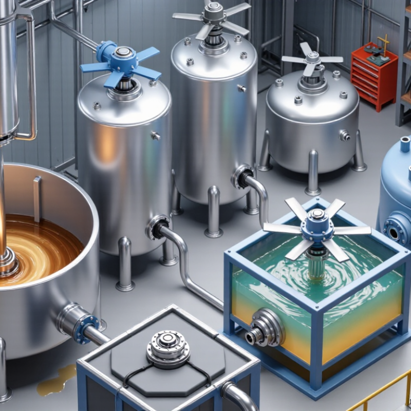
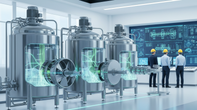
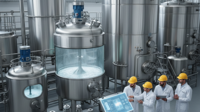
Industrial tank mixers are mechanical systems that move liquids, suspend solids, or blend ingredients inside a vessel. A motor turns an impeller, usually through a shaft entering from the tank roof or side. The impeller pushes fluid outward, downward, or around the tank, depending on its shape and position. This flow reduces concentration differences and helps prevent material from settling. It is not just stirring. The goal may be even temperature, consistent composition, or reliable transfer to the next process.
Mixer performance depends on more than motor power. Tank diameter, liquid depth, viscosity, batch size, and baffles all affect circulation. For example, baffles can reduce a deep central vortex and improve movement from top to bottom. A low-viscosity liquid may need a different impeller from a thick coating or slurry. Operators should also consider shaft clearance, seal design, cleaning access, and whether the mixer runs continuously or in batches.
Small details matter.
Even careful calculations leave some uncertainty; product behavior can change with temperature or solids loading. Pilot testing can help, though it takes time.
Choosing an industrial tank mixer starts with the process, not the motor size. Measure viscosity at operating temperature, and note whether it changes during the batch. Record tank diameter, liquid depth, outlet position, and internal obstructions. A thick fluid near the tank floor may need a different flow pattern from a thin liquid requiring gentle blending. Small details matter. Include solids content and target mixing time in the specification, too.
Power use deserves attention, but one statistic cannot size a mixer. The U.S. Department of Energy’s 2014 sourcebook, Improving Motor and Drive System Performance, reports that motor-driven systems account for about 68% of electricity use in U.S. manufacturing. This is an industry-wide figure, not a mixer-specific benchmark. Still, it supports checking motor efficiency, speed control, and expected operating hours alongside purchase cost. A smaller motor is not automatically more efficient if it runs longer or leaves product poorly mixed.
Match wetted materials to the liquid’s chemistry and cleaning routine. Check shaft length, impeller clearance, seal access, and whether maintenance can be done without emptying the vessel. Ask for performance evidence using comparable fluid properties and tank geometry. Test before purchase. A calculation can look precise while missing temperature swings or changing solids. Pilot trials may expose those gaps, though they add time and cost.
| Mixer Type | Typical Flow Pattern | Best Suited For | Key Advantages | Important Selection Factors | Common Installation |
|---|---|---|---|---|---|
| Hydrofoil impeller mixer | Predominantly axial flow | Low-viscosity liquids, blending, and keeping solids suspended | Efficient circulation with relatively low shear and power demand | Check tank geometry, impeller diameter, operating speed, liquid depth, and the solids’ settling behavior. | Usually top-entry; baffles are often used in round tanks to limit swirling. |
| Pitched-blade turbine mixer | Combined axial and radial flow | General-purpose blending, heat-transfer duties, and moderate solids suspension | Versatile flow pattern that works across a broad range of routine mixing tasks | Consider blade angle, speed, required circulation, liquid viscosity, and whether tank baffles are needed. | Commonly top-entry, with the impeller mounted on a vertical shaft. |
| Radial-flow turbine mixer | Strong radial discharge with local turbulence | Gas dispersion, liquid-liquid dispersion, and processes needing high shear | Creates intense mixing near the impeller and can disperse gas into a liquid | Assess gas rate, shear sensitivity, power input, foaming tendency, and the need for baffles. | Typically top-entry; impeller position and sparger arrangement affect performance. |
| Anchor mixer | Close-clearance circulation near the vessel wall | Viscous products, pastes, and materials that benefit from wall sweeping | Helps reduce stagnant regions near vessel walls and supports heat transfer in jacketed tanks | Match the clearance and shaft torque to product viscosity; assess whether a scraper or secondary agitator is required. | Usually top-entry, with an anchor-shaped element fitted close to the tank wall. |
| Helical-ribbon mixer | Axial circulation for high-viscosity materials | Highly viscous liquids and pasty products that are difficult to circulate with standard impellers | Moves material through the vessel while limiting the large stagnant zones common in high-viscosity service | Evaluate viscosity across the full process, torque, ribbon-to-wall clearance, and batch size. | Generally top-entry; vessel and ribbon geometry should be designed as a matched system. |
| Side-entry mixer | Directional circulation through a large tank | Large storage tanks requiring blending or suspension without a top-mounted drive | Can be practical for large tanks and may be installed without removing a roof-mounted assembly | Check tank diameter, liquid level, nozzle location, seal arrangement, and whether multiple units are needed. | Mounted through a side nozzle, commonly at an angle to direct circulation through the tank. |
| Magnetic-drive mixer | Depends on the internal impeller design | Sealed vessels and processes where minimizing a rotating shaft penetration is important | Magnetic coupling can transmit torque without a conventional dynamic shaft seal through the vessel wall | Confirm vessel pressure and temperature limits, coupling capacity, cleanability, and compatibility with the process fluid. | Often installed on a vessel top or bottom using a sealed magnetic coupling arrangement. |
Industrial tank mixers differ by flow pattern, viscosity range, and vessel geometry. An axial-flow propeller moves liquid up or down through the tank, helping blend low-viscosity fluids. A radial-flow turbine pushes liquid outward and suits gas dispersion or strong local shear. Pitched-blade turbines combine axial and radial movement, making them useful for general-purpose blending. Small details matter. Impeller clearance, baffles, and fill level can change performance as much as the mixer style.
For thick products, anchor mixers sweep close to the tank wall, while helical-ribbon designs move viscous material through a slow, controlled circulation path. Side-entry mixers can keep large storage tanks moving without a top-mounted drive. Bottom-entry designs are another option when vessel access or layout limits other installations. The U.S. Department of Energy’s 2022 Industrial Decarbonization Roadmap estimates that industry contributes about 30% of U.S. energy-related emissions, making efficient process design worth attention. That figure is not mixer-specific. In practice, the neat categories blur: some fluids change viscosity during processing, and a mixer that works at startup may struggle later. Pilot testing and checking motor load under real conditions can prevent costly surprises.
Choosing a tank mixer starts with the material, not the equipment catalogue. For thin liquids, a propeller mixer can create broad circulation with relatively low power. A turbine mixer may suit blending or gas dispersion when stronger local shear is useful. Check the flow pattern in the actual tank; baffles, fill level, and inlet position can change performance.
Thicker products need a different approach. Anchor mixers sweep close to the vessel wall and can help move viscous materials gently. Helical ribbon mixers are often considered for very thick pastes, where ordinary impellers may leave slow-moving zones. For powders, suspensions, or difficult emulsions, a high-shear mixer can break up agglomerates—but excessive shear may damage sensitive ingredients or add unwanted heat. Small details matter.
Match the mixer to the full process window: viscosity at operating temperature, batch volume, solids content, required blend time, and cleaning needs. Ask for performance data using a representative fluid, not water alone. Water is a poor stand-in for many products. Also review shaft loads, seal arrangements, and access for maintenance. One selection can look right on paper and still create a dead zone near the tank floor. That is worth checking before installation.
Selecting among the 7 best tank mixers for industrial use starts with the tank, not the catalog. Confirm vessel dimensions, liquid viscosity, solids content, and required turnover before choosing an impeller and drive. During installation, check that the support structure can handle mixer weight and operating forces. Keep the shaft aligned, secure fasteners, and verify clearances against the tank walls and internals. Small errors matter.
The U.S. Department of Energy’s 2014 U.S. Industrial and Commercial Motor System Market Assessment Report estimates that motor-driven systems use about 68% of U.S. manufacturing electricity. That figure is not mixer-specific, but it shows why efficient operation deserves attention. Match motor capacity to the actual process, and use speed control where changing batch conditions justify it. Record current draw, vibration, and temperature at a stable operating point; these readings help identify changes early. Avoid running an empty tank unless the equipment instructions permit it.
Maintenance needs a routine, not a last-minute rescue. Inspect seals for leakage, listen for new bearing noise, and check shaft runout during scheduled shutdowns. Follow the manufacturer’s lubrication intervals and isolate power before service. Keep a simple log of repairs and process settings. One practical flaw: operators may record readings inconsistently, making trends harder to trust. Standardize the check, then review it with the people who run the mixer daily.