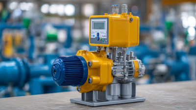
Choosing the right metering pump is not a simple catalogue decision. It is a process-design decision involving fluid behavior, pressure, accuracy, materials, and maintenance access. A pump that performs well with clean water may struggle with viscous polymer, abrasive slurry, or chlorine solution. The details matter. A cold morning can change viscosity. A blocked injection quill can change discharge pressure within seconds.
Industry forecasts show why this choice deserves careful attention. Grand View Research valued the global metering pump market at approximately USD 7.4 billion in 2023. Its report projects continued growth through 2030, supported by water treatment, chemical processing, pharmaceuticals, and energy applications. The International Society of Automation also emphasizes measurement accuracy, control stability, and equipment reliability in automated process systems. These priorities directly affect pump selection.
James P. Brenden, author of the Metering Pump Handbook, offered a practical principle: “A metering pump must be selected for the application, not merely for its capacity.” That warning remains useful. Flow rate alone cannot define a suitable metering pump. Engineers should check turndown ratio, maximum discharge pressure, pulsation, seal compatibility, NPSH conditions, and control signals. API 675 provides a recognized framework for controlled-volume positive-displacement pumps, but standards do not replace field judgment.
The uncomfortable truth is that selection can still be imperfect. Vendor curves may reflect ideal laboratory conditions. Real fluids contain bubbles, particles, and temperature changes. A reliable choice therefore combines documented data, pilot testing, operator experience, and a maintenance plan that works beside the actual equipment.
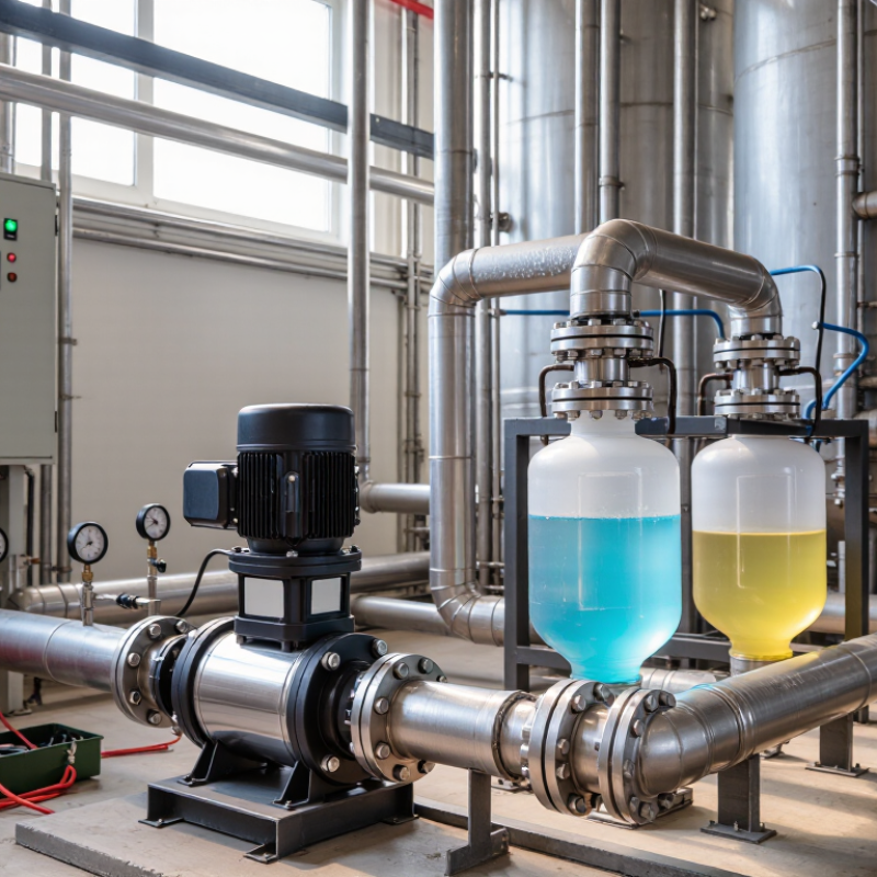
A metering pump transfers controlled volumes of liquid at regular intervals. Its job is accuracy, not simply movement. In water treatment, dosing, and process systems, small flow errors can change product quality or chemical balance. Diaphragm and plunger designs are common choices. Diaphragm pumps reduce leakage risks, while plunger pumps can handle higher pressures. Selection depends on flow rate, discharge pressure, fluid viscosity, temperature, and chemical compatibility.
Begin with the required dosing range, not the pump’s maximum capacity. A pump rated for 100 liters per hour may perform poorly when continuous control requires only 2 liters. Check turndown capability, pulse frequency, calibration methods, and the accuracy stated under real operating conditions. I have seen systems fail because operators measured flow at low pressure only. That test was incomplete. Pulsation dampeners, back-pressure valves, and suitable tubing can improve delivery stability. Materials must also tolerate the fluid over time, not just during initial testing.
Tips: Record the actual flow rate. Verify pressure at the pump outlet. Inspect valves for crystallized residue. Calibrate after maintenance. Keep a simple dosing log. If the liquid changes temperature, test again. Small details matter. A final practical check is often missed: confirm that the pump can start reliably after long idle periods.
Choosing a metering pump starts with the process, not the catalog. Define the required flow rate, discharge pressure, fluid temperature, and operating hours. A pump should handle normal demand and reasonable variation. Oversizing can reduce control accuracy and increase wear. Undersizing may cause unstable dosing during peak demand. Fluid properties matter greatly. Viscosity, abrasiveness, gas content, and chemical compatibility affect pump performance and material selection. Always check real operating conditions, not only room-temperature data.
In field applications, I have found that control range is often underestimated. A pump may deliver the target rate, yet perform poorly at low flow. Check turndown ratio, stroke frequency, response time, and calibration methods. Pulsation can also influence mixing, pressure readings, and downstream equipment. A dampener or suitable control strategy may be necessary. Do not rely on a single datasheet value. Confirm calculations with the manufacturer’s technical documentation and, when possible, a controlled trial.
Tips: Record the fluid’s actual temperature and concentration. Verify pressure at the injection point. Ask whether the fluid can crystallize or release gas. Plan for inspection and calibration access. Leave room for adjustment. No selection is perfect. Process conditions change, and the original assumptions may need review after commissioning. Track flow accuracy over time instead of trusting the initial setting. Small errors become important when dosing continues for months.
How to Choose the Right Metering Pump?
Pump selection starts with fluid behavior, not catalog capacity. In field commissioning, I compare diaphragm, plunger, and peristaltic designs against pressure, viscosity, temperature, and dosing accuracy. Diaphragm pumps suit corrosive chemicals and leak-sensitive systems. Plunger pumps deliver higher pressure and stable flow, but their seals require careful inspection. Peristaltic pumps protect the fluid path inside flexible tubing, although tubing fatigue can reduce accuracy. The U.S. Department of Energy reports that pumping systems may consume 25–50% of energy in some industrial facilities. Efficient control matters, even for small chemical feed systems.
Materials decide service life. Polypropylene and PVDF resist many aggressive fluids, while 316L stainless steel handles demanding temperatures and mechanical loads. PTFE diaphragms tolerate strong chemical exposure, but they may not suit every abrasive slurry. Check concentration charts, permeability data, and temperature limits. Never trust material names alone. The International Energy Agency reports that motor-driven systems use roughly half of global electricity, making variable-speed control and correctly sized motors important. API 675 also emphasizes controlled-volume pump performance, repeatability, and testing. A clean spreadsheet can still mislead. I recheck actual discharge pressure, pulsation, and calibration after installation. Small errors become expensive over thousands of operating hours.
Comparing pump types by typical maximum flow capacity and pressure capability.
These representative industry ranges help narrow the selection: plunger pumps are generally suited to very high pressure, while peristaltic and progressive cavity pumps can handle higher flow rates. Actual performance depends on viscosity, temperature, chemical compatibility, pulsation requirements, and system design.
Choosing the right metering pump starts with three numbers: flow rate, pressure, and chemical conditions.
Calculate flow from daily demand. For example, dosing 240 liters per day requires an average flow of 10 liters per hour. Check minimum, normal, and peak demand before selecting capacity. A practical design might require 10 liters per hour but specify a 12–15 liter per hour range. Small errors matter. Confirm the real output with a calibration column or timed container.
Pressure means total differential pressure, not discharge pressure alone.
Add injection pressure, static lift, pipe friction, fittings, and any backpressure valve. If the injection point requires 3 bar and piping losses equal 0.6 bar, the pump must produce at least 3.6 bar. A modest safety margin is useful, but oversizing can reduce control accuracy and increase energy waste.
The U.S. Department of Energy reports that pumping systems can represent about 25% of industrial motor energy use in its Pumping System Sourcebook.
Chemical compatibility requires more than checking the chemical name.
Record concentration, temperature, pH, solids, and exposure time. Review wetted materials, including the diaphragm, seals, valves, and tubing. A material may resist a dilute solution but fail under heat or higher concentration. Use resistance charts, safety data sheets, and manufacturer compatibility testing. Then verify performance under actual pressure. This step is often rushed, and that is a mistake. Track calibration drift after installation.
How to Choose the Right Metering Pump?
Installation, Calibration, Maintenance, and Safety Considerations
A metering pump performs best when installation details receive careful attention. Mount it on a rigid, level base near the chemical storage point. Keep it level. Use piping with the correct diameter and avoid unnecessary bends. A suction line that is too long may create unstable flow. Install isolation valves, a pressure relief device, and suitable backflow protection. Confirm that every wetted component matches the chemical, temperature, and operating pressure.
Calibration should reflect actual site conditions, not only factory data. Measure discharged volume with a graduated cylinder or calibrated vessel. Record the result at several stroke lengths and speeds. I once trusted a nominal setting and found a noticeable dosing error after installation. That mistake changed my practice. Calibrate again after changing pressure, tubing, or chemical concentration. Do not guess.
Maintenance requires a written inspection routine. Check connections for leaks, inspect diaphragms and valves, and remove crystallized residue before it hardens. Keep accurate service records. During maintenance, isolate power and pressure, then flush the system using an approved procedure. Wear chemical-resistant gloves, eye protection, and protective clothing. Good ventilation matters too. Never rely on smell to identify a hazard. Review the safety data sheet and applicable workplace requirements before handling any process chemical. A neglected relief path can turn a small blockage into a serious failure.
| Decision Area | Key Parameter | Recommended Practice or Typical Value | Selection and Operating Guidance | Verification Point |
|---|---|---|---|---|
| 1. Pump Selection | ||||
| Pumping principle | Diaphragm, plunger, peristaltic, or solenoid-driven design | Use diaphragm pumps for general chemical dosing; plunger pumps for high-pressure service; peristaltic pumps for abrasive or shear-sensitive fluids. | Match the pump principle to fluid compatibility, required pressure, accuracy, solids content, and acceptable pulsation. | Confirm the pump curve and material compatibility before purchase. |
| Required capacity | Normal, minimum, and maximum flow rate | Size the pump so the normal operating point is typically between 30% and 80% of its rated capacity. | Avoid selecting a pump that operates continuously at its maximum stroke length, speed, or rated flow. | Compare the required operating range with the manufacturer's certified performance data. |
| Discharge pressure | Operating pressure and system pressure variation | Specify the maximum discharge pressure, including static head, friction loss, injection pressure, and foreseeable pressure increases. | The pump's maximum allowable discharge pressure must exceed the actual system pressure. Never use a pump beyond its pressure rating. | Measure pressure at the pump discharge or at the injection point under normal flow conditions. |
| Flow accuracy | Required dosing accuracy and repeatability | Many positive-displacement metering pumps can achieve approximately ±1% to ±2% repeatability under stable, calibrated conditions. | Actual accuracy depends on fluid viscosity, pressure stability, pulsation, temperature, valve condition, and calibration method. | Verify performance using a timed-volume, gravimetric, or flow-meter calibration test. |
| Fluid properties | Viscosity, temperature, solids, gas content, and vapor pressure | Record the full operating range rather than using only the fluid's room-temperature properties. | High viscosity may reduce capacity; abrasive solids accelerate wear; entrained gas can cause loss of prime; high vapor pressure can increase cavitation risk. | Obtain a current safety data sheet and process-fluid specification. |
| Wetted materials | Head, diaphragm, valves, tubing, seals, and fittings | Select materials based on chemical resistance at the actual concentration and temperature. | Common materials include plastics, elastomers, stainless steels, and specialized alloys; compatibility must be confirmed for each wetted component. | Check chemical compatibility tables and validate with the fluid supplier where necessary. |
| Control method | Manual, pulse, analog, or digital process control | Use pulse or analog control when dosing must track flow, tank level, conductivity, pH, or another process variable. | For variable-flow systems, a flow-proportional signal or feedback control can help maintain a consistent concentration. | Confirm signal type, range, fail-safe behavior, and electrical classification. |
| Pressure protection | Relief valve, back-pressure valve, and check valve | Install an appropriately sized pressure-relief device where a blocked discharge could create unsafe pressure. | A back-pressure valve may improve accuracy, while a check valve helps prevent reverse flow. These devices do not replace one another. | Set and test protective devices according to the system design and applicable regulations. |
| 2. Installation | ||||
| Mounting location | Accessibility, environment, and elevation | Install on a rigid, level support with sufficient clearance for inspection, calibration, and component replacement. | Protect the pump from flooding, excessive heat, direct sunlight, vibration, and corrosive vapors. Follow the stated ambient temperature range. | Confirm that operators can safely reach isolation valves, fittings, controls, and emergency shutoffs. |
| Suction arrangement | Suction lift, flooded suction, and line size | A flooded suction is generally preferred, especially for high-viscosity, volatile, or difficult-to-prime fluids. | Keep the suction line short, adequately sized, and free from unnecessary elbows. Excessive suction lift can cause cavitation or loss of prime. | Check suction pressure, pipe routing, strainer condition, and all connections for air leakage. |
| Piping connections | Pipe support, alignment, and leak prevention | Support piping independently so that external loads are not transferred to the pump head or fittings. | Use the correct tubing, thread sealant, gasket, and tightening method for the connection material. Do not overtighten plastic fittings. | Perform a controlled leak and pressure test before introducing hazardous chemicals. |
| Injection point | Location, quill, and mixing conditions | Place the injection point where adequate turbulence or mixing is available and where the fluid will not immediately separate or settle. | Use an injection quill or suitable check assembly when backflow, crystallization, or high process pressure is possible. | Confirm that the injection point remains submerged or correctly positioned during all operating conditions. |
| Electrical installation | Voltage, grounding, enclosure, and isolation | Follow the pump nameplate and electrical diagram for supply voltage, frequency, fuse protection, and grounding. | Install a lockable disconnect and provide overcurrent protection. Hazardous locations require appropriately certified equipment and installation methods. | Have electrical work completed and tested by qualified personnel. |
| Priming and venting | Removal of air and safe chemical introduction | Prime through the designated priming or vent valve using the correct procedure for the fluid. | Vent the pump head to a safe collection point. Never loosen fittings while the pump is pressurized or operating. | Check for stable discharge, absence of air bubbles, and correct suction and discharge pressure. |
| 3. Calibration and Commissioning | ||||
| Calibration method | Timed-volume or gravimetric measurement | Run the pump at the intended stroke, speed, pressure, and fluid temperature, then collect and measure the output over a known time. | Use a graduated cylinder for basic checks or a calibrated balance/flow meter for higher confidence. Measure more than once and average the results. | Document pump settings, fluid conditions, test duration, measured volume or mass, and calculated flow. |
| Calibration calculation | Flow rate | Flow rate = collected volume ÷ test time. Convert units consistently, such as L/h or mL/min. | For gravimetric testing, convert mass to volume using the fluid density at the test temperature. | Compare measured flow with the required setpoint and record the deviation. |
| Calibration points | Minimum, normal, and maximum operating settings | Calibrate at multiple points when the pump operates over a wide range or when accurate proportional dosing is required. | Repeat calibration after changes in pressure, fluid concentration, temperature, tubing, diaphragm, valves, or control settings. | Keep calibration records with date, instrument identification, operator, and acceptance criteria. |
| System commissioning | Functional and alarm testing | Test start/stop control, low-level protection, loss-of-flow detection, pressure alarm, leak detection, and emergency shutdown. | Verify that the pump stops or enters the intended safe state when a critical fault occurs. | Record test results and correct all abnormal readings before placing the system into routine service. |
| 4. Maintenance | ||||
| Routine inspection | Leaks, noise, vibration, heat, and pressure | Inspect during each operating shift or according to the site's risk-based maintenance plan. | Unexpected noise, pulsation, temperature rise, flow loss, or visible leakage may indicate worn valves, a damaged diaphragm, blockage, or air ingress. | Compare observations with the pump's normal operating baseline. |
| Valve and strainer care | Check valves, foot valves, and suction strainers | Clean strainers and inspect valve seats, balls, springs, and seals at planned intervals. | Deposits, crystallization, or solids can prevent valves from seating and cause inaccurate or interrupted dosing. | Inspect more frequently when the fluid contains suspended solids or is prone to crystallization. |
| Diaphragm and seal replacement | Wear parts and replacement interval | Replace according to condition, operating hours, chemical exposure, and the maintenance schedule. | Do not wait for a hazardous leak or total loss of flow. Use replacement materials rated for the actual chemical and temperature. | After replacement, prime, leak-test, and recalibrate the pump. |
| Lubrication and drive inspection | Gearbox, bearings, motor, and coupling | Use only the lubricant type and quantity specified for the drive assembly, where lubrication is required. | Inspect coupling alignment, mounting bolts, motor condition, and gearbox oil for contamination or abnormal wear. | Isolate and lock out the energy source before removing guards or accessing moving parts. |
| Recalibration interval | Verification frequency | Verify at commissioning, after major maintenance, and at an interval based on process criticality and historical drift. | Critical dosing systems may require more frequent checks than non-critical utility applications. | Define an acceptance limit and a documented response when the pump falls outside it. |
| 5. Safety Considerations | ||||
| Personal protective equipment | Protection against chemical exposure | Use PPE selected from the fluid safety data sheet, typically including chemical-resistant gloves, protective eyewear, protective clothing, and suitable footwear. | Additional respiratory or face protection may be required for volatile, toxic, corrosive, or aerosol-forming chemicals. | Make the safety data sheet and emergency equipment readily accessible. |
| Isolation and depressurization | Lockout/tagout and stored energy | Stop the pump, isolate suction and discharge, depressurize, drain, and flush the system before maintenance. | Electrical energy, hydraulic pressure, trapped chemical, and rotating components can remain hazardous after shutdown. | Verify zero energy and zero pressure before opening the pump head or piping. |
| Chemical containment | Spill control and drainage | Provide secondary containment sized for the installation risk and use compatible drain or collection arrangements. | Do not discharge chemical residues into drains unless permitted by local regulations and the site's waste-management procedure. | Inspect containment, hose connections, and leak detection devices regularly. |
| Pressure hazards | Blocked discharge and dead-heading | Protect every positive-displacement pump against blocked discharge with a correctly selected relief system. | Never close a discharge isolation valve while the pump is running unless the system is specifically designed and protected for that condition. | Test pressure-relief devices at the required interval and keep discharge paths unobstructed. |
| Compatibility and reaction risk | Mixing chemicals and cross-contamination | Use separate, clearly identified lines and equipment for incompatible chemicals. | Prevent backflow between chemical storage tanks and process lines. Some chemical combinations can generate heat, gas, or toxic products. | Review the process hazard assessment and chemical incompatibility information. |
| Operating documentation | Procedures, training, and records | Maintain written procedures for startup, shutdown, priming, calibration, maintenance, spill response, and emergency isolation. | Only trained and authorized personnel should operate or service the metering pump. | Keep training records, inspection reports, calibration data, and maintenance history up to date. |
| 6. Final Selection Checklist | ||||
| Application fit | Capacity, pressure, accuracy, and fluid compatibility | All four requirements must be satisfied simultaneously across the complete operating range. | A pump that meets flow requirements but lacks chemical compatibility or pressure capacity is not suitable. | Obtain written confirmation of the duty point and material suitability. |
| Lifecycle cost | Energy, spare parts, labor, downtime, and disposal | Evaluate total cost of ownership rather than purchase price alone. | Accessible wear parts, stable calibration, efficient control, and reliable leak prevention can reduce operating costs. | Compare expected maintenance frequency and critical spare-parts requirements. |
| Compliance | Applicable codes, workplace rules, and environmental requirements | Review local electrical, pressure, chemical handling, environmental, and occupational safety requirements. | Requirements vary by location, industry, chemical, and installation classification. | Complete a documented engineering and safety review before final installation. |